Assessing Tank Lime Dosing and Mixing Performance at Oswestry WTW
Oswestry WTW consists of an inlet works and a series of gravity sand filters before the untreated water enters the Clear Water Tank (CWT). Chlorine dosing takes place at the three CWT inlets and lime slurry dosing takes place near the two CWT outlets. The lime dosing is required to adjust the pH of the water. The existing lime slurry preparation and dosing plant was to be replaced with a new lime water or a slurry preparation and dosing system due to evidence of poor mixing.
Our Approach
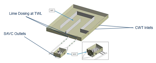
The CWT outlets connect to the Self Acting Valve Chamber (SAVC), which has four inlets and three outlets. The three SAVC outlet lines exit the works via a non-return valve chamber, where water sampling was implemented. The mixing performance of the existing works downstream of the CWT was unknown and so a CFD analysis was conducted to assess the mixing performance of the proposed dosing with a 0.15% w/w concentration of lime water and a 2% w/w concentration of lime slurry. Figure 1 shows the CFD model geometry.
Figure 1: CFD Model of Oswestry CWT & SAVC
CFD analyses were conducted using a multi component mixture of water and lime water slurry with appropriate density and viscosity properties of each component. Transient simulations were conducted as the flow patterns were not steady. The Coefficient of Variance (CoV) at each of the three SAVC outlets was assessed and compared to the target of 0.05. The range of CWT process flows was considered (130 – 210 ML/d) with the corresponding lime water dosing (~7100 to ~87700 L/h) and lime slurry dosing (513-4348 L/h).
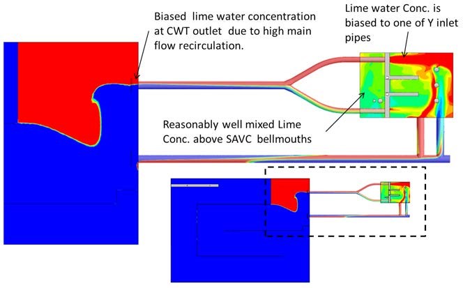
The CFD analyses were conducted for each process condition, investigating the flow patterns and mixture concentrations, hence the CoV at the SAVC outlets was assessed. Figure 2 shows the lime concentrations for one of the process conditions, indicating that the lime was reasonably well mixed at the SAVC outlets, even though there were high lime concentrations at some of the SAVC inlets.
Figure 2: Lime Concentration
Conclusion
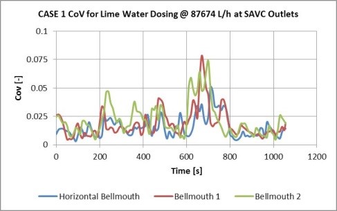
Due to the transient nature of the flow within the SAVC, the CoV was predicted to vary with time (as shown in Figure 3). Analysis determined that the lime water mixing was slightly better than the lime slurry dosing. In some cases, the peak CoV exceeded the target of 0.05, although in all cases the time averaged CoV was below the well mixed target value of 0.05.
Figure 3: Transient Coefficient of Variation
Added Value
MMI provided the capability to assess lime mixing within the CWT, self-acting valve chamber and inter-connecting pipework to determine that the proposed lime water dosing was marginally better than lime slurry dosing. The study involved the design of a proposed sparge pipe arrangement for the lime water dosing and confirmed that no further mixing equipment was required.
For more information surrounding our CFD Analysis capabilities in the Water Industry, please contact us on 0117 960 2212 (Bristol) or email us.


