[fusion_builder_container hundred_percent=”yes” overflow=”visible”][fusion_builder_row][fusion_builder_column type=”1_1″ background_position=”left top” background_color=”” border_size=”” border_color=”” border_style=”solid” spacing=”yes” background_image=”” background_repeat=”no-repeat” padding=”” margin_top=”0px” margin_bottom=”0px” class=”” id=”” animation_type=”” animation_speed=”0.3″ animation_direction=”left” hide_on_mobile=”no” center_content=”no” min_height=”none”][fusion_text]
Introduction
Darchem Engineering Ltd is supporting the Darlington Retube and Feeder Replacement (RFR) project in Ontario, CA. During the project, the volume of reactor components will have to be reduced within the radioactive waste processing building which will be achieved using flasks loaded with irradiated components. In order to satisfy the safety case, in the event of a flask falling, an energy absorber or impact crash mat is required to ensure the demands on the flask are reduced to an acceptable level.
Description of energy absorber
The proposed energy absorber is constructed from a honeycomb structure encased within a thin stainless- steel box structure as shown in Figure 1. The honeycomb is continuous over its height and is formed from pressure-folded steel sheets which are then resistance welded together.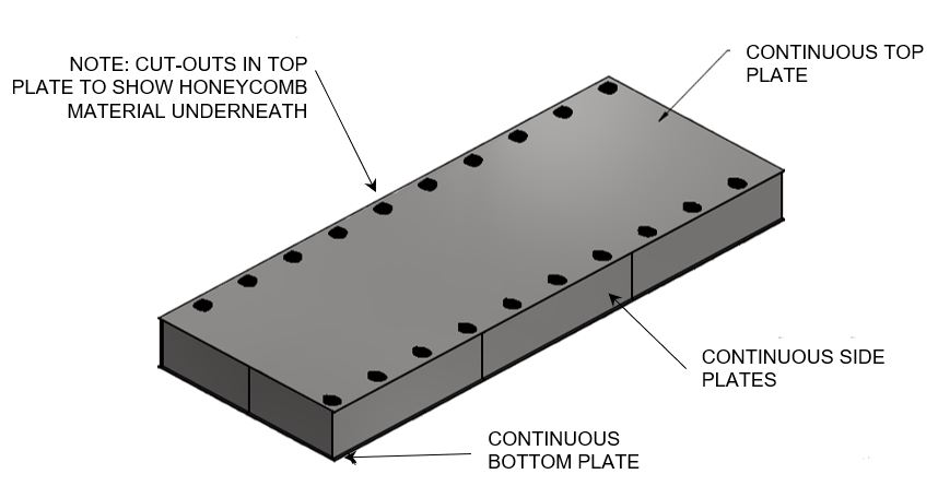
Figure 1: Energy absorber layout
Methodology
The objective of the analyses is to numerically evaluate the dropped impact performance of the energy absorber assembly for 5 different drop scenarios (an example is shown in Figure 2).
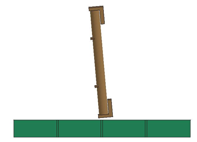
Figure 2: Example drop scenario
Due to the complex arrangement, the analysis methodology was based on the finite element (FE) method which allows the capture of multiple complex interactions including contact and non-linear strain- rate dependent material behaviour.
Finite element representations of the EF Flask, PT/CT Flask, and crash pad involved in the drop impact scenarios were developed and the resultant models solved using the explicit software LS-Dyna.
Results
The results concentrated on investigating the level of damage and deformation within the honeycomb and the amount of plastic strain within the surrounding steel plate to ensure acceptable performance.

Figure 3: Typical deformation of energy absorber
The contact force was also extracted (Figure 4) and used to demonstrate that the forces remained below the previously determined withstand of the flasks.
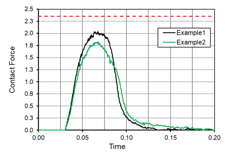
Figure 4: Example contact force time-history
MMI provided initial results and an iterative approach was used in collaboration with both Darchem and the end client to come up with an acceptable final design.
The Outcome
MMI provided engineering justification for the energy absorber by means of non-linear finite element analysis. The results of this analysis were used to support its use within Darlington Nuclear Power Station.[/fusion_text][/fusion_builder_column][/fusion_builder_row][/fusion_builder_container]