[fusion_builder_container hundred_percent=”yes” overflow=”visible”][fusion_builder_row][fusion_builder_column type=”1_1″ background_position=”left top” background_color=”” border_size=”” border_color=”” border_style=”solid” spacing=”yes” background_image=”” background_repeat=”no-repeat” padding=”” margin_top=”0px” margin_bottom=”0px” class=”” id=”” animation_type=”” animation_speed=”0.3″ animation_direction=”left” hide_on_mobile=”no” center_content=”no” min_height=”none”][fusion_text]MMI Engineering’s Dr. Sean Malkeson, a Senior Staff Engineer based in Warrington, has helped to secure funding from the UK Fluids Network for two Special Interest Groups (SIGs). The two SIGs are:
- Sprays in engineering applications: modelling and experimental studies; and
- Combustion science, technology and applications.
The SIGs aim to bring world-leading UK groups together to identify topics for collective explorations in the engineering application of sprays and combustion. The groups will not only identify and tackle the major contemporary challenges in their fields, but they will also disseminate knowledge and engage with the public on the importance of improving our understanding of such phenomena.
Dr. Malkeson, who has expertise in RANS simulations, a-priori DNS modelling, stratified mixture and droplet combustion – as well as accidental fire and explosion simulations, will act as an industrial contact for the SIGs. As a visiting researcher at the Combustion Research Group at Newcastle University (led by Prof. Nilanjan Chakraborty), Dr. Malkeson will continue to engage in research for combustion and spray applications.
If you would like to receive further information on the SIGs or the Combustion Research Group, please contact Dr. Malkeson directly (SMalkeson@MMIEngineering.com).
The following diagrams are taken from Dr. Malkeson’s recent presentation, “Analysis of fuel mass fraction dissipation rate transport in turbulent flame-droplet interaction: A Direct Numerical Simulation study”, at the 27th European Conference on Liquid Atomization and Spray Systems. The presentation examined the modelling of the fuel mass fraction dissipation rate and its transport equation in the context of RANS simulations for the combustion of fuel sprays in a turbulent environment.
[/fusion_text][/fusion_builder_column][fusion_builder_column type=”1_2″ last=”no” spacing=”yes” center_content=”no” hide_on_mobile=”no” background_color=”” background_image=”” background_repeat=”no-repeat” background_position=”left top” hover_type=”none” link=”” border_position=”all” border_size=”0px” border_color=”” border_style=”” padding=”” margin_top=”” margin_bottom=”” animation_type=”” animation_direction=”” animation_speed=”0.1″ animation_offset=”” class=”” id=””][fusion_imageframe lightbox=”no” gallery_id=”” lightbox_image=”” style_type=”none” hover_type=”none” bordercolor=”” bordersize=”0px” borderradius=”0″ stylecolor=”” align=”none” link=”” linktarget=”_self” animation_type=”0″ animation_direction=”down” animation_speed=”0.1″ animation_offset=”” hide_on_mobile=”no” class=”” id=””] 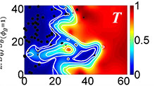 [/fusion_imageframe][/fusion_builder_column][fusion_builder_column type=”1_2″ last=”yes” spacing=”yes” center_content=”no” hide_on_mobile=”no” background_color=”” background_image=”” background_repeat=”no-repeat” background_position=”left top” hover_type=”none” link=”” border_position=”all” border_size=”0px” border_color=”” border_style=”” padding=”” margin_top=”” margin_bottom=”” animation_type=”” animation_direction=”” animation_speed=”0.1″ animation_offset=”” class=”” id=””][fusion_imageframe lightbox=”no” gallery_id=”” lightbox_image=”” style_type=”none” hover_type=”none” bordercolor=”” bordersize=”0px” borderradius=”0″ stylecolor=”” align=”none” link=”” linktarget=”_self” animation_type=”0″ animation_direction=”down” animation_speed=”0.1″ animation_offset=”” hide_on_mobile=”no” class=”” id=””]
 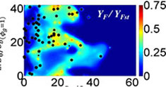 [/fusion_imageframe][/fusion_builder_column][fusion_builder_column type=”1_2″ last=”no” spacing=”yes” center_content=”no” hide_on_mobile=”no” background_color=”” background_image=”” background_repeat=”no-repeat” background_position=”left top” hover_type=”none” link=”” border_position=”all” border_size=”0px” border_color=”” border_style=”” padding=”” margin_top=”” margin_bottom=”” animation_type=”” animation_direction=”” animation_speed=”0.1″ animation_offset=”” class=”” id=””][fusion_text]
Contours of non-dimensional temperature, T, after 2.0 chemical time scales on the mid x-z plane for a representative Direct Numerical Simulation Case. The white lines are the iso-lines of the reaction progress variable which rises monotonically from 0 in the unburned reactants on the left to 1 in the fully burned products on the right in steps of 0.1. The black dots indicate the fuel droplets which have been enlarged for visualisation purposes.
[/fusion_text][/fusion_builder_column][fusion_builder_column type=”1_2″ last=”yes” spacing=”yes” center_content=”no” hide_on_mobile=”no” background_color=”” background_image=”” background_repeat=”no-repeat” background_position=”left top” hover_type=”none” link=”” border_position=”all” border_size=”0px” border_color=”” border_style=”” padding=”” margin_top=”” margin_bottom=”” animation_type=”” animation_direction=”” animation_speed=”0.1″ animation_offset=”” class=”” id=””][fusion_text]
Contours of normalised fuel mass fraction, YF / YFst, after 2.0 chemical time scales on the mid x-z plane for a representative Direct Numerical Simulation Case (N.B. The black dots indicate the fuel droplets and droplet sizes are not shown to scale).
[/fusion_text][/fusion_builder_column][/fusion_builder_row][/fusion_builder_container]