Mixing in Anoxic Zones
Anoxic zones are used for biological denitrification. An optimal design ensures that the flow is well mixed and that there is no short circuiting. Therefore, it is essential that the biological solids are maintained in suspension and do not settle out within the anoxic zone. MMI was appointed by a UK water company, which was constructing two new ASP lanes as part of an improvements scheme, to assess the anoxic zones using Computational Fluid Dynamics (CFD). Two anoxic zones, located upstream of the aeration lanes, were to be supplied with a mixture of settled sewage effluent from the primary tanks and Return Activated Sludge (RAS) from the final settlement tanks. Mixing of these two fluid streams takes place upstream of the anoxic zones. Each anoxic zone was mixed using a radial bottom flow impeller. The geometry of the anoxic zones is presented in Figure 1.

Figure 1: Anoxic Zones and Aeration Lane
Modelling the Flow
The basic hydrodynamics were generated from a three dimensional model of the geometry, with boundary conditions applied to represent inflow and outflow. A dye trace experiment was utilized so that short circuiting could be examined, and so that the overall mixing characteristics could be understood and evaluated against ‘tanks in a series’. A multiphase model was used to assess the settlement of solids, and the rotation of the impellers was modelled by their geometry and an appropriate multiple reference frame model.
Results
Figure 2 presents an example of the combined residence time distribution of the two anoxic zones compared to the theoretical distribution for two tanks in series. The results demonstrate that the two anoxic zones in series closely represent two perfectly stirred tanks.
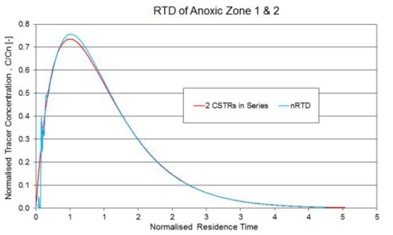
Figure 2: Residence Time Distribution for the Anoxic Zones 1 & 2
Figure 3 shows contours of sludge concentration on a vertical plane through the centre of the mixers. This shows that the solids are well mixed within the anoxic zones, but there is some solids accumulation at the bottom of the inlet chamber. This could be easily corrected by infilling the chamber up to the level of the inlet pipe.
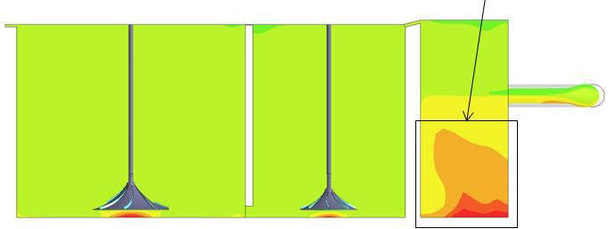
Figure 3: Solids Accumulation in the Inlet Chamber
Value Added
The use of CFD enabled the new design to be assessed faster and at much lower expense when compared against the use of scaled physical models.
For more information surrounding our flow modelling capabilities in the Water Industry, please contact us on 0117 960 2212 (Bristol) or email us.