Optimisation of Pump Sumps
The operating capacity and efficiency of pumps are affected by the hydrodynamics of the flow approaching them. This is due to the pump impellers, which are designed with the assumption that flow approaches the impeller axially. Nonideal flow conditions are usually influenced by the geometry of the wet well, operation of the pump(s), and depth of water in the sump. Examples of non-ideal flow include:
- Pre-swirl of flow approaching
- Free surface vortex formation
- Submerged vortex formation
- Spatial asymmetry of the flow
- Temporal fluctuations (turbulence) in the flow
Pre-swirl of the flow at the pump intake causes the flow to approach the impeller at an angle, which can result in a change in pump performance, cavitation damage, and load fluctuations if the preswirl is not constant. Free surface and submerged vortices can influence the pump capacity, impose a fluctuating load on the pump impeller blades, lead to destructive resonance, and may induce cavitation of the impeller blades.
Our Approach
In the design of pump sumps, it is generally required to demonstrate that:
- No organised free surface and/or subsurface vortices of greater magnitude than Type 2 shall enter the pump
- The level of pre-swirl, i.e. swirl angle, should be less than 5° from the axial direction and should be steady
- Time-averaged velocities measured at eight locations in the pump throat should be within ± 10% of the spatial mean of time-averaged velocities
- The temporal fluctuations of velocities measured at each of the eight locations should be less than 10% of the average velocity measured at that location
At MMI, we use Computational Fluid Dynamics (CFD) to make these assessments and confirm a new design or optimisation of an existing pump sump. An example showing the identification of freesurface and submerged vortex structures is shown in Figure 1. Figure 2 presents streamlines showing non-uniform approach flow in a series of pump bays.
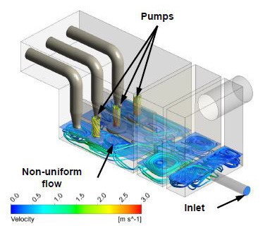
Figure 1: Streamlines (Left) and Surfaces Identifying Vortex Structures (Right) Within the Region of a Pump Intake
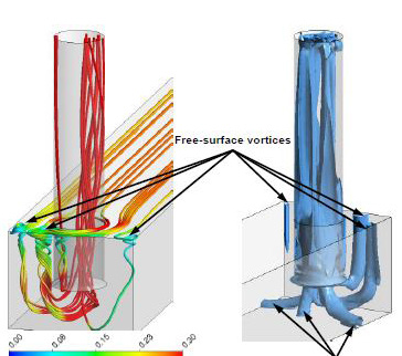
Figure 2: Streamlines Coloured by Velocity
Using CFD, the performance of a pump sump may be analysed over a range of flow conditions and water levels, together with an investigation of the effect of geometry changes, in order to optimise the operating performance of the pumps.
For more information surrounding our CFD capabilities in the Water Industry, please contact us on 0117 960 2212 (Bristol) or email us.