Optimising Solids Distribution and Mixing in Anoxic Selector Tank
At Weston-Super-Mare planned improvements included a new four lane activated sludge plant. Upstream of the aeration lanes, an inlet zone referred to as an Anoxic Selector Tank recieves settled sewage effluent from the primary tanks and return activated sludge from the final settlement tanks.
Within the Anoxic Selector Tank the two streams of fluid and solids are mixed and distributed through two submerged penstock weirs. In order to achieve an even solids distribution through the penstock weirs adequate mixing is required within the tank to homogenise the solids.
The concept design is shown in Figure 1. The RAS discharges through a bellmouth connected to a vertical pipe within the tank and the settled sewage liquor discharges through a horizontal pipeline connected to the side of the tank close to the base.
MMI Engineering was asked to investigate the solids distribution and mixing of the solids using Computational Fluid Dynamics.
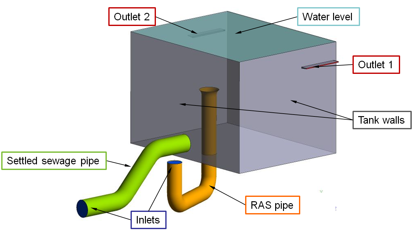
Figure 1: Concept Design
It was found in the concept design that at high flow, when the momentum of the discharge through the RAS pipe was high, the RAS would tend to short circuit to Outlet 2 as shown in Figure 2 and therefore generate a mal-distribution of RAS. The flow bias towards Outlet 2 was due to a skewed velocity profile at the bellmouth caused by the upstream bend and insufficient distance between the bend and bellmouth for a symmetrical velocity profile to develop. Insufficient mixing within the tank, as shown by the large variation in RAS concentration, results in a mal-distribution of the RAS.
To improve mixing within the tank the vertical pipe was removed. This was so that the RAS discharge was located at the base of the tank so that the two fluid streams interact close to the point of discharge where the kinetic energy and hence mixing energy is greatest. Two baffles were also included in order to generate an inner mixing zone and to prevent any short circuiting of solids. Figure 3 shows a significantly more uniform solids distribution as a result of these changes and hence, a more uniform distribution of solids through each of the submerged penstock weirs.
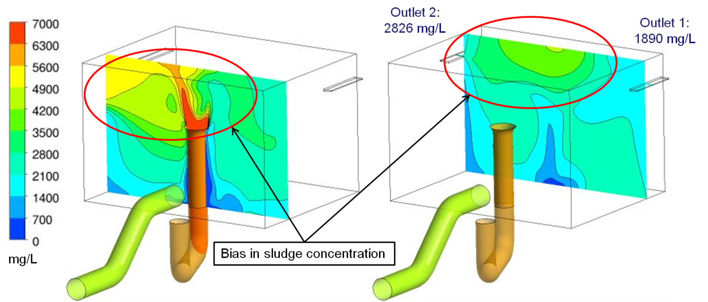
Figure 2: Poor Mixing Within the Concept Design
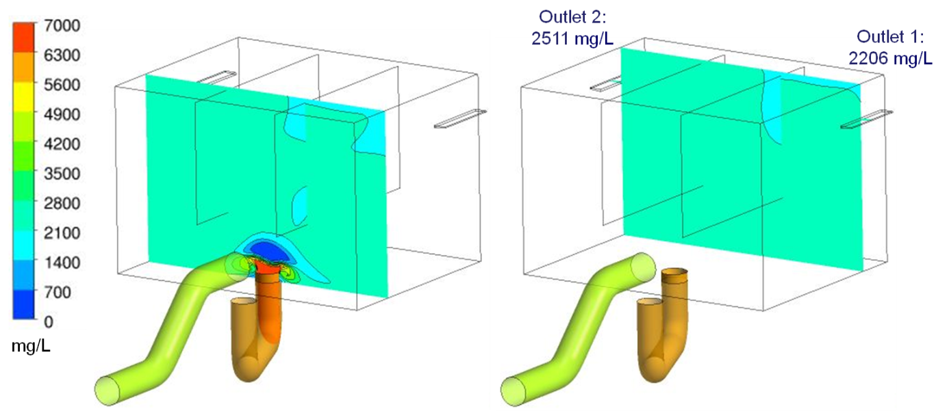
Figure 3: Improved Mixing as a Result of Design Changes Recommended by MMI
Value Added
The use of Computational Fluid Dynamics and MMI Engineering’s experience of mixing and solids distribution aided the improvement of the mixing tank resulting in a system with a good solids distribution over a range of flow rates.
For more information surrounding our modelling capabilities in the Water Industry, or to discuss your Wastewater Treatment Works project requirements, please contact us on 0117 960 2212 (Bristol) or email us.